An informative article from Tom Woods, owner of Tom Woods Custom Driveshafts, simplifying the changes made to a Jeep's driveline following installation of a lift kit.
Okay, so now you've done it. You put that lift in your vehicle or changed the engine, transmission or transfer case or differential maybe all of the above and now your go anywhere four wheel drive baby rides like a out of balance washing machine. Or now that you've got all that raw power & torque you keep breaking your drive shaft. What do you do? The lift kit manufacturer may tell you one thing and the local drive line shop or mechanic will tell you another. You certainly haven't put this much time, effort and money into creating the ultimate 4X4 to live in fear of the possible catastrophic consequences which can come about (usually at the worst possible moment) from neglecting drive line considerations.
So what do you do? Who do you believe? Larger joints? Possibly a C.V.? Quite frankly, only YOU can answer these questions. As with many of our problems in life the solution can usually be found by arming yourself with information. Unfortunately for you there is a lot of mis-information out there especially regarding proper "U" joint angles. I hope to clear up a lot of this here. Please bear in mind that we are not working with an exact science. Some of the time things that in theory should work, do not, and other times people seem to be happy with a drive-line that by all standards should cause a horrible vibration or short life. Although your chances for success are greater if you do your homework and design around established principles.
My opinions and recommendations are based on numerous sources of information and 18 years of personal experience. By no means do I know all there is to know about drive lines (or any thing else). The intent here is to give broad general information, realizing that for the most part we are dealing with highly modified vehicles, requiring other than factory approved solutions.
In addition to a straight and properly balanced driveline, proper geometry is the most important design factor to consider when smoothness of operation, ultimate strength and long life are desired.
If you are like me, rather than relying on just what someone may tell you, you tend to believe something more readily if you have a basic understanding of the principles involved. It is very important that you understand the concept of non-uniform velocity of your drive line caused the "U" joints working through an angle:
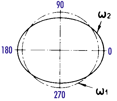
If you were to watch a "U" joint move through an angle (the operating angle) from an end view, you would see that the joint in the driven shaft has to move through an ellipse. Because the joint has to move through each of the quadrants of this elliptical path in a fixed amount of time, the velocity or surface speed of the driven shaft increases & decreases two times per revolution.
With a conventional two joint drive shaft, if your second "U" joint has an equal or intersecting angle, the second "U" joint will be decelerating at the same time and at very near the same rate that the first "U" joint is accelerating, resulting in a smooth power flow through to your pinion.

Now I hope you noticed I stated "very near" when describing this cancellation of non-uniform velocities. This is because the rates of acceleration and deceleration, minimum and maximum velocity , are NOT reciprocal numbers. Min./Max. velocities are a function of the cosine of the operating angle. If for example; to make the numbers easy, the cosine of the angle were .90 and the velocity on the driving shaft were 100 F.P.S. the min. velocity would be 90 F.P.S. and the max velocity would be 111 F.P.S. It is for this reason that on your drivel shaft there is an upper limit to how steep you can run a drive shaft, even with equal or intersecting angles.
So, How steep can you run a drive shaft? Again, this is entirely up to you, however, most manufacturers recommend a maximum of 7 degrees. I personally believe they are conservative (they have to be). I also think they base their recommendations on the math for the largest semi-sized driveline and call it good for every thing else (which it would be). Doing the math for an automotive sized driveline, using a 4" swing diameter and assuming the transfer case out-put and pinion shafts are parallel, the actual cosine for an angle of 15 degrees. I calculate the result of the net difference in linear distance traveled through the arc of each of the "U" joints path, to be roughly .0014" per occurrence. I believe there are enough clearances in the universal joint, the slip yoke & spline stub along with a torsional modulus of elasticity in the tubing and other components to accommodate this. Beyond this point the the power train components must themselves flex and distort to allow for this extra motion. This repetitive and continuous flexing will fatigue these components and cause premature failure.
There are other factors to consider though, beginning with what you are willing to live with. Bear in mind that with a driveline pushed to this 15 degree limit you may notice a slight (slight can be a matter of definition) vibration on smooth highway at about 45-50 M.P.H. when you flutter the gas just right. Most people can live with this. When in doubt or if you are near this upper limit, I recommend that you install a double cardan (C.V. ) type drive shaft.

Remember that the geometry you need to maintain is different from that of a conventional 2 joint driveline. The cost differential is minimal and the performance/life gain will pay for itself in the long run.
Another factor seldom considered is the vibrations which will be caused by the forces required for acceleration & deceleration of the mass of your driveline. A driveline which is too heavy and/or having radius which is too large along with running through a steep angle can accentuate a problem here.
Also, you need to know your "U" joint life expectancy. Basically a "U" joint is rated for specific, continuous operating load @ 3000 R.P.M. for 5000 hours with a 3 degree joint angle, and assuming proper periodic maintenance. If you double the angle you halve the life, halve the load & double the life and vice/versa. Where your driveline seldom sees a constant load, "U" joint life becomes a difficult number to crunch. While 5000 hours may not seem like much it's roughly equal to driving 8 hours a day, 5 days a week for 2-1/2 years. So 20% of life expectancy may not be such a bad number after all.
Most drive shafts will, depending on components used, incur a binding interference at about 30 degrees. You DO NOT, I repeat DO NOT want to run a drive shaft at any where near this angle. You need to allow for axle droop, frame flexing and differential roll. All of which can momentarily alter the operating angle of the "U" joint to the point that it will cause what I refer to as an IMMEDIATE & CATASTROPHIC FAILURE. Ultimately you need to be certain that your driveline will rotate freely under full axle droop.
It is also very important that you consider the upward pinion movement, caused by spring wrap, on the differential under high torque situations. You can usually get a pretty good idea of how much the differential will roll up with the following simple test:
After making certain that all of your power train is in good working order, and while standing a safe distance to the side of the vehicle where you can watch the motion of the differential. Have a partner set the park/emergency brake, start the vehicle, put transfer-case in low range, the transmission in 1st. gear and accelerate the engine moderately. I think it may well surprise you how much spring wrap you actually have. Again it may be necessary to do something to control the upward motion of the pinion to prevent driveline binding and that big CRUNCH/SNAP which often occurs in high torque situations.
Many people mistakenly believe that a double cardan or C.V. type drive shaft will allow for greater operating angles than a conventional two joint or single cardan drive shaft. This is not true. Some types of C.V.'s will actually incur a binding interference at less of an angle than a standard two joint drive line, again depending on the individual components used. Additionally the C.V. itself is longer than more conventional components and will create a greater operating angle on the driveline, especially on very short shafts.
The real benefit to a C.V. (double cardan) drive shaft is smoother operation at higher operating angles and longer life. The C.V. assembly works by intersecting the joint angles at the center pivot point and delivering a smooth rotational power flow or surface velocity through the drive line. Therefore, with this type of driveline it is important to roll the differential upward so that you have minimal joint operating angle at the differential end. As any substantial joint angle would cause the pinion to try to speed up & slow down two times per revolution. Causing what is known as a torsional vibration (Torsional vibrations will also be created in a two joint driveline that has unequal angles at each of the "U" joints). Rolling the differential upward will lessen the total operating angle at each end of the driveshaft. Now at the transfer case end of the driveshaft you have two joints equally dividing the total angle. This will double the life of the joints at this end, additionally you will be back up to full rated life for the joint at the differential end. I also believe a C.V. is stronger than a conventional driveline when turning through the same angle. This would be the result of transmitting the torque in a plane more perpendicular to the centerline of the driveshaft.
One word of caution though, make sure the pinion tail bearing still receives adequate oil. An over-fill may be required, overfilling the differential may cause a problem with foaming of the differential fluid. Adding about a cup of a Dextron type II automatic transmission fluid to your gear oil will lower the surface tension of the oil and should help control the foaming. Additionally while this rolling of the differential is easily done with the rear, front ends create a different problem. Unless you are willing to cut the differential housing away from the tubes and reweld, anything you do to correct for driveline angles up front will adversely effect the steering geometry of your vehicle. Most people do just what is done in the factory every day. That is, make some kind of a compromise, get things as right as possible for the high speed rear shaft and live with less than ideal performance from the generally lower speed less used front shaft.
Now that you know enough to determine which type of driveline you need for your particular application, you will want to size it properly for the expected load. Again, you will need to do some homework. How much does your vehicle weigh? What gear ratios do you have? How about your driving habits? How much break away torque is required for wheel slip? What transfer-case & differential do you have? Would you really rather break a T-case, axle or pinion shaft before the "U" joint?
Many people call or write telling me about their 600 h.p. engine and to ask me to determine the proper "U" joint or size of driveline for their application. The truth of the matter is; that this much horsepower if delivered through the powertrain at a low R.P.M. would require the same sized driveline as used in a 18 wheel semi tractor rig, while if delivered at 5000 R.P.M. The stock joint in a C.J. could easily handle it. " U" joints and other driveline related components are rated by torque. With horsepower as a constant, torque and speed are inseparably related and inversely proportional. Torque is what you need to be concerned with. Consider if you will the relatively low h.p. winch motor that delivers 9000 lbs. or more in pulling power, but, your V6 engine would have a very difficult time pulling a trailer of equal weight at a high speed. Additionally many engines are rated for peak h.p. at an absurdly high R.P.M. which is seldom seen in a real world situation.
There are many situations which will cause "U" joint or other parts to break which are not caused by under-sized components. One of the most common is just plain poor quality. There are many differences from brand to brand, among them are; The quality and alloy of the steel used, cast or forged?, design, machine tolerances held and sheer bulk. My experience has been that Spicer components are generally superior in strength, durability and precision to any other readily available brand.
Other possible causes for "U" joints breaking could shock load (If you're going up a hill and your wheels start to slip, is your solution to put the pedal to the metal?). Most fractures are the result of high stress impact loads, or binding interference's caused by excessive/uncontrolled differential roll or droop.
Quite often I see joints which fail in one direction only.
Usually, if the joint is of good quality which allows for proper greasing, the problem is caused by a damaged or mis-aligned attaching yoke.
If you have a problem with repetitive premature wear out of your joints, look for this. If you install a good joint in a damaged or mis- aligned yoke the needle bearings will not make full contact across the trunion . This will crush the bearings and if allowed to progress will actually cause the joint to over heat and melt down. This type of failure can be extremely hazardous and costly especially if it occurs at a high speed. A simple check for this type of problem is to install a "U" joint of known good quality into the suspect part and turn the joint by hand through its range of motion to check that the joint moves freely with no rough spots. My rule on questionable parts is; "When in doubt, throw it out". After all the part is cheap when compared to the cost of a break-down which can cause even more damage to your rig.Twisted tubes are another common problem. Greater strength can be obtained in many ways, among them are: larger diameters, heavier wall thickness and better quality.
The factors to consider when selecting tube size and type are: length, speed / R.P.M., straightness and strength required. The most common types of tubing available are cold rolled electric welded (C.R.E.W.), drawn over mandrel (D.O.M.), and to a lesser degree the much hyped chrome molly. Factory drive shafts are built using a C.R.E.W. This type of tube is made through a process of using flat sheets of steel, running it through a series of rollers to form the tubular shape and electric welding the seam. D.O.M. tube is initially made the same way with an additional step of drawing the tube over a die or mandrel. This step is a lot like a cold forging process which serves to make the tube much straighter, rounder, stress relieved and stronger. Although it appears to be, D.O.M. tube is not a true seamless tube. Seamless tube is generally made in very heavy wall thickness's and is usually used for hydraulic applications. Chrome molly tube is an alloy tube and also made with a very heavy wall thickness. The down side to using a tube of an exceptionally heavy wall thickness is as outlined previously, the acceleration and deceleration of mass along with the excessive radial load placed on the adjoining support bearings. Also the construction methods require either turning down the insert diameters of the attaching components or enlarging the inside diameter of the tube to accept off the shelf components. Machining the I.D. of the tube will leave a weak point where thin material meets thick. Additionally the net gain in yield & tensile strength from D.O.M. to chrome molly is very minor.
In order to select the proper tube size you need to know the length of the finished driveline, expected speed/ R.P.M., torque requirements and allowable clearances. Because of something known as the critical speed, drive shafts are built on different sized tubes. If you were to support a length of any shafting or tube at the ends, you would find that the shaft or tube will flex in the center. This flexing will increase at greater lengths and higher speeds because of the radial forces applied from minor unbalance, reaching point to which vibrations will become uncontrollable and finally the ultimate destruction of the drive shaft at critical speed. Larger diameter tubes may be used to span greater lengths and/or to run at higher R.P.M., however, torque is also a factor in determining critical speed. In theory at least, with enough torque critical speed can be reduced to zero. Although this critical speed at zero R.P.M. would seldom be a factor in a normal four wheel drive application.
In summary, for a custom application, you need to know the answers the questions of Angles, Torque, Length, R.P.M., Life expectancy and how smooth you expect your ride to be while traveling down the highway.
If you understand and apply the concepts that I've attempted to convey here and do your homework. You should be able to specify the size and type of drive line you may require as well as anybody and better than most. Please, at least give serious consideration to all of the factors involved when doing any vehicle modification rather than just the obvious end result of more lift, bigger engine etc. After all it really is a lot less expensive to do the job right the first time.

